SRFxx Sonic Range Finder Reader
This example shows how to read a Devantech SRFxx , an ultra-sonic range finder which communicates via the I2C synchronous serial protocol, using Arduino's Wire Library.
The I2C protocol involves using two lines to send and receive data: a serial clock pin (SCL) that the Arduino Master board pulses at a regular interval, and a serial data pin (SDA) over which data is sent between the two devices. As the clock line changes from low to high (known as the rising edge of the clock pulse), a single bit of information - that will form in sequence the address of a specific device and a a command or data - is transferred from the board to the I2C device over the SDA line. When this information is sent - bit after bit -, the called upon device executes the request and transmits it's data back - if required - to the board over the same line using the clock signal still generated by the Master on SCL as timing.
Because the I2C protocol allows for each enabled device to have it's own unique address, and as both master and slave devices to take turns communicating over a single line, it is possible for your Arduino to communicate with many devices (in turn) while using just two pins of your microcontroller.
Hardware Required
Arduino Board
Devantech SRFxx Range Finder (models SRF02, SRF08, or SRF10, click to compare)
100 uf capacitor
hook-up wires
breadboard
Circuit
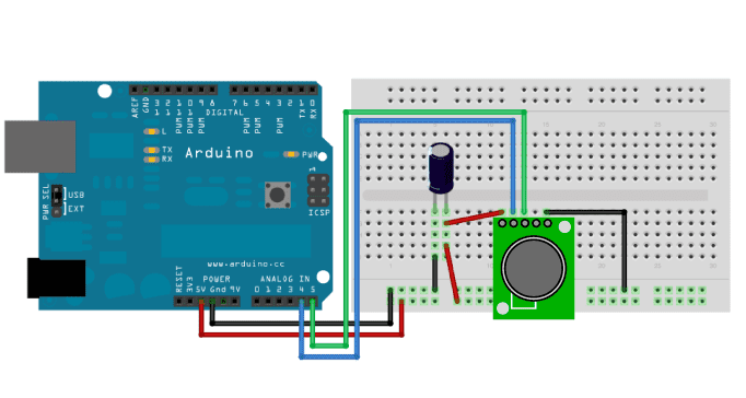
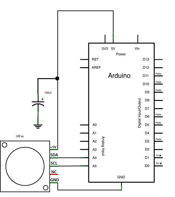
Attach the SDA pin of your SRFxx to analog pin 4 of your board, and the SCL pin to analog pin 5. Power your SRFxx from 5V, with the addition of a 100uf capacitor in parallel with the range finder to smooth it's power supply.

image developed using Fritzing. For more circuit examples, see the Fritzing project page
Schematic

Code
- If using two SRFxxs on the same line, you must ensure that they do not share the same address. Instructions for re-addressing the range finders can be found at the bottom of the code below. *
// I2C SRF10 or SRF08 Devantech Ultrasonic Ranger Finder
// by Nicholas Zambetti <http://www.zambetti.com>
// and James Tichenor <http://www.jamestichenor.net>

// Demonstrates use of the Wire library reading data from the
// Devantech Utrasonic Rangers SFR08 and SFR10

// Created 29 April 2006

// This example code is in the public domain.

#include <Wire.h>

void setup() {

  Wire.begin();                // join i2c bus (address optional for master)

  Serial.begin(9600);          // start serial communication at 9600bps
}

int reading = 0;

void loop() {

  // step 1: instruct sensor to read echoes

  Wire.beginTransmission(112); // transmit to device #112 (0x70)

  // the address specified in the datasheet is 224 (0xE0)

  // but i2c adressing uses the high 7 bits so it's 112

  Wire.write(byte(0x00));      // sets register pointer to the command register (0x00)

  Wire.write(byte(0x50));      // command sensor to measure in "inches" (0x50)

  // use 0x51 for centimeters

  // use 0x52 for ping microseconds

  Wire.endTransmission();      // stop transmitting

  // step 2: wait for readings to happen

  delay(70);                   // datasheet suggests at least 65 milliseconds

  // step 3: instruct sensor to return a particular echo reading

  Wire.beginTransmission(112); // transmit to device #112

  Wire.write(byte(0x02));      // sets register pointer to echo #1 register (0x02)

  Wire.endTransmission();      // stop transmitting

  // step 4: request reading from sensor

  Wire.requestFrom(112, 2);    // request 2 bytes from slave device #112

  // step 5: receive reading from sensor

  if (2 <= Wire.available()) { // if two bytes were received

    reading = Wire.read();  // receive high byte (overwrites previous reading)

    reading = reading << 8;    // shift high byte to be high 8 bits

    reading |= Wire.read(); // receive low byte as lower 8 bits

    Serial.println(reading);   // print the reading

  }

  delay(250);                  // wait a bit since people have to read the output :)
}

/*

// The following code changes the address of a Devantech Ultrasonic Range Finder (SRF10 or SRF08)

// usage: changeAddress(0x70, 0xE6);

void changeAddress(byte oldAddress, byte newAddress)

{

  Wire.beginTransmission(oldAddress);

  Wire.write(byte(0x00));

  Wire.write(byte(0xA0));

  Wire.endTransmission();

  Wire.beginTransmission(oldAddress);

  Wire.write(byte(0x00));

  Wire.write(byte(0xAA));

  Wire.endTransmission();

  Wire.beginTransmission(oldAddress);

  Wire.write(byte(0x00));

  Wire.write(byte(0xA5));

  Wire.endTransmission();

  Wire.beginTransmission(oldAddress);

  Wire.write(byte(0x00));

  Wire.write(newAddress);

  Wire.endTransmission();

}

*/
See Also
Wire Library - Your reference for the Wire Library.
DigitalPotentiometer - How to control an Analog Devices AD5171 Digital Potentiometer.
Master Reader/Slave Writer - Two Arduino are programmed to communicate with one another in a Master Reader/Slave Sender configuration via the I2C.
Master Writer/Slave receiver - Two Arduino are programmed to communicate in a Master Writer/Slave Receiver configuration via the I2C.
Last revision 2018/05/17 by SM