Arduino 101 Curie Timer One PWM
With this tutorial you learn to use one of the timers available in the microcontroller to generate a PWM signal. The Pin selected for the signal is Pin 13 and this will blink the on-board LED. The period of the signal is 1 second (1000000 microseconds) and the duty cycle is set at 25%. The waveform generation, once started, just goes on. In the loop() you can put your code and that won't interefere with PWM signal unless you use timer functions.
Hardware Required
The Circuit

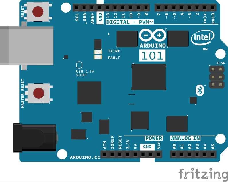
image developed using Fritzing. No additional hardware is needed to use this tutorial.
Software Essentials
Libraries
CurieTimerOne.h is the library that provides access to the Timer 1 of the microcontroller. This library allows to set up the number of microseconds that the timer counts before it asserts an interrupt. The interrupt can be configured to call a specific function - the callback function - and each interrupt increments a counter. The same library is used to generate a PWM signal with duty cycle and period lenght fully customizable.
Functions
None
Code
#include "CurieTimerOne.h"

void setup() {

  // Setup a PWM signal on pin 13, onboard LED, with a 25% duty cycle

  // of a 1 second period (1000000 usec), as follow (please note the

  // decimal point to indicate double):

  CurieTimerOne.pwmStart(13, 25.0, 1000000);

  // Or, use discrete number range, 0-1023, to define the duty period,

  // 255 is 24.9%, as follow:

  // CurieTimerOne.pwmStart(13, 255, 1000000);
}

void loop() {

  // put your main code here, to run repeatedly:

  delay( 10000 );
}
See Also
Last revision 2016/03/13 by SM