How to use the Arduino GSM shield with Arduino Leonardo, Arduino Yun, and Arduino Mega
The GSM shield communicates with an attached Arduino through the Software Serial library. By default, this communication uses digital pins 2 and 3. On the Uno this works without modification, but to use the Leonardo, Yun, or Mega boards, some slight changes are required.
The GSM_TX pin, pin 2 on the shield, sends information to the Arduino. The Arduino relies on an interrupt on this pin to know when information is available to read. On the Uno, this interrupt capability is on pin 2. The Leonardo, Yun, and Mega have interrupt capabilities on different pins.
You do not need to change any code to program the shield for use with the Leonardo, Yun, or Mega, as the library will change the Arduino's RX pin automatically depending on the board selected in the "Tools" menu of the IDE. You do, however, need to re-route the GSM_TX data to the appropriate pin on the Arduino.
Arduino Leonardo and Arduino Yun
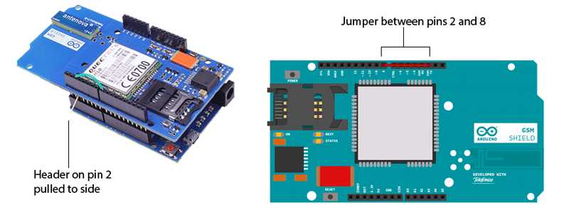
The GSM library uses digital pin 8 to communicate with the Leonardo or the Yun. Thus, you need to route the signal from pin 2 of the GSM shield to pin 8 of the Arduino, and at the same time prevent this signal from connecting to pin 2 of the Arduino. The following two steps accomplish this:
On the GSM shield, connect a jumper wire between digital pins 2 and 8. This routes the signal from pin 2 of the GSM shield to pin 8 of the Arduino.
To prevent this signal from interfering with or being interfered by pin 2 of the Arduino, bend the male header attached to pin 2 on the GSM shield to the side so it does not connect to the Leonardo or Yun.

Arduino Mega
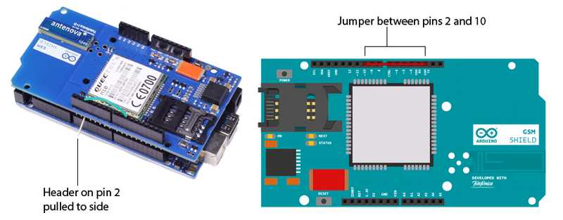
The GSM library uses digital pin 10 to communicate with the Mega. Thus, you need to route the signal from pin 2 of the GSM shield to pin 10 of the Arduino, and at the same time prevent this signal from connecting to pin 2 of the Arduino. The following two steps accomplish this:
On the GSM shield, connect a jumper wire between digital pins 2 and 10. This routes the signal from pin 2 of the GSM shield to pin 10 of the Arduino.
To prevent this signal from interfering with or being interfered by pin 2 of the Arduino, bend the male header attached to pin 2 on the GSM shield to the side so it does not connect to the Mega.

Using alternate pins with the library
If you prefer to use a different interrupt pin for communication, refer to the Software Serial library reference page to see valid pin choices. You will need to change the __RXPIN__ definition in the GSM3SoftwareSerial.cpp file, located in the GSM library folder.
For more information on using the GSM Shield, visit the Arduino GSM Shield Getting Started guide.
The text of the Arduino getting started guide is licensed under a Creative Commons Attribution-ShareAlike 3.0 License. Code samples in the guide are released into the public domain.