TFT and connecting to other Arduino boards
Even if the screen's headers are designed to fit into the socket on the front of the Arduino Esplora or the Arduino Robot but, this module is compatible with any AVR-based Arduino (UNO, Leonardo, etc...) or with the Arduino Due. If you want to use one these other boards, some slight changes on connections are required.
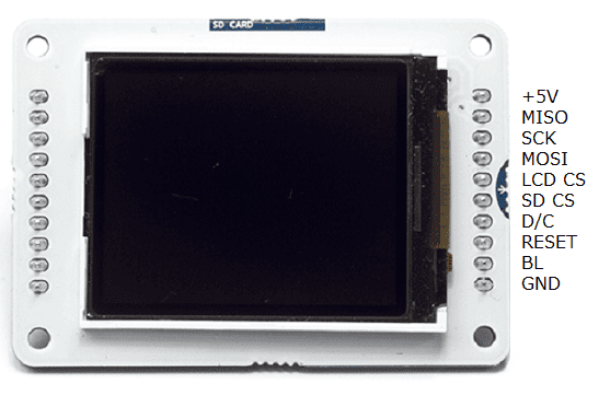
You can either connect the screen with hardware SPI pins, or define your own set of pins. Using the hardware SPI is faster when drawing to the screen.
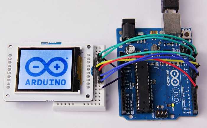
Arduino Uno
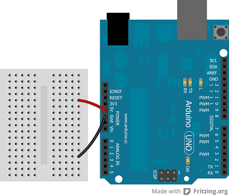
Connect power and ground to the breadboard.
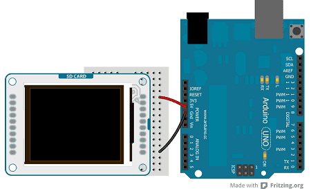
Connect the screen to the breadboard. The headers on the side of the screen with the small blue tab and arrow should be the ones that attach to the board. Pay attention to the orientation of the screen, in these images, it is upside down.
Connect the pins following this default configuration:
| +5V: | +5V |
| MISO: | pin 12 |
| SCK: | pin 13 |
| MOSI: | pin 11 |
| LCD CS: | pin 10 |
| SD CS: | pin 4 |
| D/C: | pin 9 |
| RESET: | pin 8 |
| BL: | +5V |
| GND: | GND |
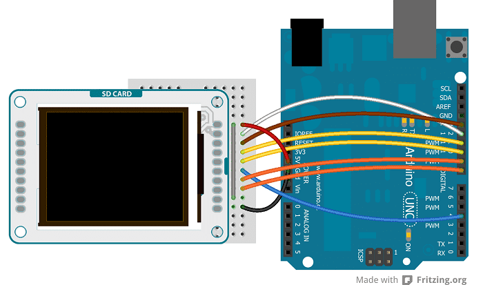
Connecting the pins in the proper way, you can see the lcd screen working with your Uno (or Duemilanove) just uploading the simple "TFTBitmapLogo" sketch.
Arduino Leonardo & Arduino Yún
The Arduino Leonardo & Arduino Yún use different pins to be compatible with the lcd screen. To set the pins MISO, MOSI and SCK, you have to use the ICSP terminals.
| +5V: | +5V |
| MISO: | Miso pin (white wire on ICSP) |
| SCK: | Sck pin (brown wire on ICSP) |
| MOSI: | Mosi pin (yellow wire on ICSP) |
| LCD CS: | pin 7 |
| SD CS: | pin 8 |
| D/C: | pin 0 |
| RESET: | pin 1 |
| BL: | +5V |
| GND: | GND |
The image below shows an Arduino Leonardo but it works for an Arduino Yún too.
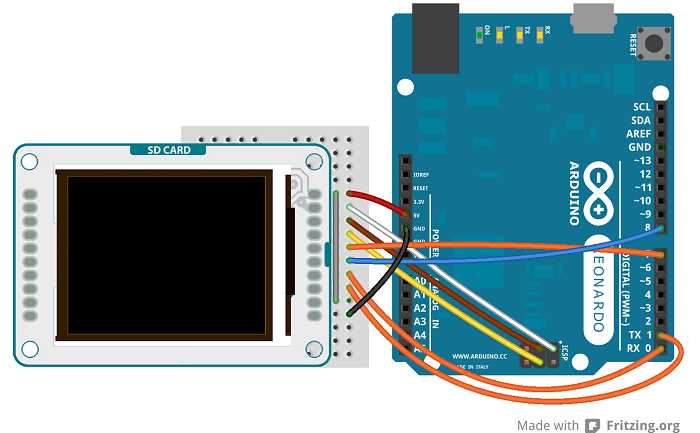
The screen will show this message: "Arduino TFT Bitmap Example. Open serial monitor to run the sketch". Open the serial monitor to view the Arduino Logo.
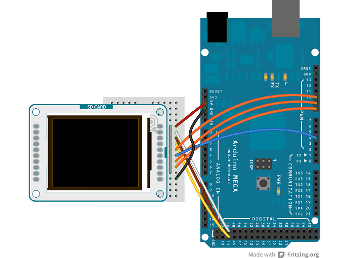
Arduino Mega 2560 or Mega ADK
To connect the lcd screen to a Mega board, use this pin configuration:
| +5V: | +5V |
| MISO: | 50 on Mega 2560 (Miso on ADK) |
| SCK: | 52 on Mega 2560 (Sck on ADK) |
| MOSI: | 51 on Mega 2560 (Mosi on ADK) |
| LCD CS: | pin 10 |
| SD CS: | pin 4 |
| D/C: | pin 9 |
| RESET: | pin 8 |
| BL: | +5V |
| GND: | GND |
Arduino Due
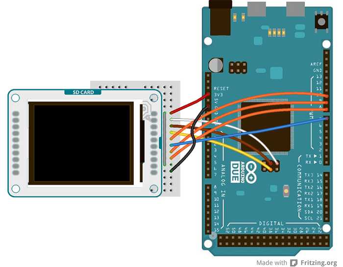
To connect the lcd screen to an Arduino Due, use this pin configuration and don't forget to set the right value for the variable "sd_cs" (#define sd_cs 7) in the sketch:
| +5V: | +3.3V |
| MISO: | Miso pin (white wire on SPI) |
| SCK: | Sck pin (brown wire on SPI) |
| MOSI: | Mosi pin (yellow wire on SPI) |
| LCD CS: | pin 10 |
| SD CS: | pin 7 |
| D/C: | pin 9 |
| RESET: | pin 8 |
| BL: | +3.3V |
| GND: | GND |
The text of the Arduino getting started guide is licensed under a Creative Commons Attribution-ShareAlike 3.0 License. Code samples in the guide are released into the public domain.